Neopixel LED controller with Arduino

Posted at: 10:12 pm on May 10, 2015 by Ismail Uddin

featured-img

If you’ve been reading my blog, you’ll know I recently got my hands on an Arduino, which means learning a new programming language, C! After playing around for a couple of weeks and getting to grips with the language, I put together a nice little project which I thought would make a great tutorial! This simple, yet really cool project will show you how to control the colour as well as number of LEDs lit up on Adafruit’s Neopixel LED rings using a single potentiometer, and a push button!

What you’ll need

  • An Arduino based board (Arduino Uno, or a similar type will do)
  • Adafruit Neopixel LED ring (12x)
  • 10k Ω (linear response) mini potentiometer
  • Push button
  • 1k Ω resistor
  • Breadboard
  • Jumper wires

_DSC4933

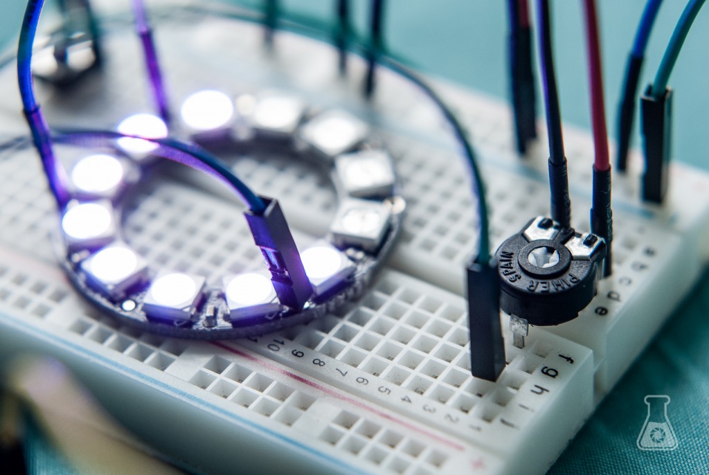
The potentiometer is the key component for this project! It is essentially a variable resistor, which is controlled by twisting the centre dial using a screwdriver. They come in a variety of forms, ranging in maximum resistance value and response (linear or logarithmic).

Wiring it all up

wiring-diag_bb

Wiring this project up is pretty trivial, the schematic makes it quite clear I think. The important concept to understand here, is that the wire from the switch to the Arduino, must go to one of the ADC  (analogue to digital converter) pins, and must be on the side of the switch connecting to GND. A resistor connects the switch to the GND, to ensure when the button is not pressed, the value is as close to 0 V as possible, on the ADC pin.

Coding the project

Before we can upload our code to the project, we’ll need Adafruit’s Neopixel library. You can download the library from here, where there are instructions on how to install the library. With the library installed, you can then upload my code to your Arduino board to run. You can download the code from my GitHub page, or copy it from below.

// Arduino code for Neopixel LED controller
// using a potentiometer and switch button
// (C) Ismail Uddin, 2015
// www.scienceexposure.com

#include <Adafruit_NeoPixel.h>
#define PIN 3
Adafruit_NeoPixel strip = Adafruit_NeoPixel(12, PIN, NEO_GRB + NEO_KHZ800);

int potPin = 2;
int val = 0;
int colorVal = 0;
int reading = 0;
int x;
int prevVal = 0;
int switchPin = 6;
boolean lastBtn = LOW;
boolean NeopixelColor = false;
boolean lastButton = LOW;


void setup() {
  // put your setup code here, to run once:
  strip.begin();
  strip.show();
  pinMode(switchPin, INPUT);

}

void loop() {
  // put your main code here, to run repeatedly:
  reading = analogRead(potPin);
  val = (reading/1024.0) * 13;
  colorVal = (reading/1024.0) * 255;
  
  if (digitalRead(switchPin) == HIGH && lastButton == LOW)
  {
    delay(250); // Account for contact debounce
    NeopixelColor = !NeopixelColor;
    
  }
  
  if (NeopixelColor == false)
  {
    // Neopixel LED number code
    strip.setBrightness(40);
    if (val != prevVal)
    {
      for ( x = 0; x < val; x++) 
      {
        strip.setPixelColor(x,255,0,255);
      }
      for (x=val; x<13; x++) 
      { 
        strip.setPixelColor(x,0,0,0);
        strip.show();
      }
      prevVal = val;
    }
    else
    {
      strip.show();
    }
    
  }
  else
  {
    // Neopixel Color code
    for (x=0; x < prevVal; x++)
    {
      strip.setPixelColor(x,colorVal,0,255-colorVal);
      strip.show();
    }
  }
}

Some key things to point out in this code:

  • If you have a larger Neopixel ring, you can use that as well, just make the necessary edit to wherever in the code a 12-LED ring is referenced. Those being in the initial first few lines where the library is initialised, and in setting the value for the variable `var` based on the potentiometer reading. Note that in this case, the value is scaled to be between 0 and 13, 1 value larger than the number of LEDs
  • The pin numbers are declared at the beginning of the code, and so you may change their value if you choose to use different pins on your Arduino
  • Currently, the code is set to only control the red and blue portion of each pixel. You can change this if you like, by adding the variable `var` in place of `y` in the `strip.setPixelColor(x,255,y,225);` statement.
  • The brightness of these Neopixel LEDs is intense! I’ve set it at measly 40/255, but you can raise it if you like from the statement `strip.setBrightness`

If you’ve wired it all up correctly, and uploaded the code, you should have your project up and running! Using a screwdriver, twist the potentiometer to control the number of LEDs lighting up. Press the button once, to switch to controlling the LED colours. Now the potentiometer will control the LED’s colour. Press the switch again to switch back to LED number mode! Cool, isn’t it? There’s a cool vine below showing you how this should work in practice!


I hope you enjoyed this tutorial! If you have any issues, please drop me a comment below and I’ll be happy to help!


Comments

  • Adam Elliott

    Hi.. Amazing tutorial, Thanks.
    But I can’t seem to find any ref to strip.setPixelColor(x,255,y,225)?

    • Hey, glad you liked it! Thanks for pointing that out, I don’t think I explained it clearly. What I meant to say was that you could add the variable ‘colorVal’ into this part of the code:

      for (x=0; x < prevVal; x++)

      {

      strip.setPixelColor(x,colorVal,0,255-colorVal);

      strip.show();

      }

      So currently the middle number is permanently set to 0 (which is the green portion of the LED). If you want, you can replace that with 'colorVal' or even an expression like '255-colorVal'. I had written the tutorial before I cleant up the code, hence why there were missing references :S

      Hope this solves your problem and it works nicely with your set up!

  • Remy Sefi

    hello, im kinda new with arduino, i have a gemma and was hoping to get a bit of help in what goes where, also i was wondering if it was possible to control both parameters led number and color with the same potentiometer but without a switch 😀 i love your work by the way 🙂

    • Hi Remy,

      Glad to you know you like my work! Are you interested in using this particular project with a Gemma? I’ll look into it and see how it could work, and get back to you soon! As for controlling both parameters without a switch, would you prefer an alternative? Because otherwise, you’d be changing both things at the same time..

      • Remy Sefi

        Yeah, it’s a potentiometer for a guitar and I want the leds to light up one by one as they change color :), and the gemma is to keep it as compact as possible :D, thanks for replying by the way, much appreciated by a noob to this like me 😛

      • Remy Sefi

        any word my good man? im really itching to get this project going 😛

        • Hey sorry for the late reply!

          I’ve had a look at Adafruit’s Gemma page, and I think the closest set up you’d be using is this one: https://learn.adafruit.com/3d-printed-led-microphone-flag/circuit-diagram

          You would probably need a 3.7 V battery to connect to the Gemma using it’s white clip pin (JST connector). The Neopixel would then connect as follows:

          IN (on Neopixel) to D0 (on Gemma)

          5V (on Neopixel) to Vout (on Gemma)

          GND (on Neopixel) to GND (on Gemma)

          The potentiometer would need to share the GND pin of the Gemma, so if you could link two wires from the Neopixel and the potentiometer by soldering, and then connect it to the Gemma? Or however else you prefer.

          The other pin of the potentiometer, would connect to the 3.3V (3Vo) pin of the Gemma. These are the two outer PINs.

          The inner PIN of the potentiometer would then connect to D2 / A1 of the Gemma. This is the same PIN, labelled on either side, and is the only analog input pin on the Gemma.

          I’ve modified the for the Gemma assuming those PINs are used:

          https://gist.github.com/ismailuddin/45b5fed916d51022b24c

          As you change the potentiometer, the number of LEDs and their colour will vary at the same time.

          Hopefully this should work with no problems! Any problems, feel free to ask 🙂

          • Remy Sefi

            it worked! i just had to change the int pot pin from 2 to A1 and now it works like a charm, thanks a lot for taking the time to help me 🙂

          • That’s brilliant! If you can record a video of it in action, that would be really cool to show off how it worked 🙂

          • Remy Sefi

            here it is, you cant really see the gemma, but the connections are the same you posted above https://instagram.com/p/-NHTq2FUD9/

          • That’s brilliant ! Glad I could help you get it working! ?

  • Jonathan Wright

    Great project! What would it look like if I wanted to instead control the brightness with one pot and then the colour with a different pot? Would there be much of a difference in the coding? Cheers 🙂

    • Thanks! 🙂 And sorry for the late reply! There wouldn’t be much difference in the coding, just some slight changes. I’ll put a code snippet here by tonight showing you how it will look!

      • Jonathan Wright

        Amazing, thankyou 🙂

  • Dexter

    I’m using a trinket to control theneopixel but I’m very confused with connection nd coding as it only has 12 pins

    • If it is this controller you are using -> https://www.adafruit.com/product/1501 , then do you mean that there are only 4 GPIO pins? The pin for the potentiometer (potPin) would need to be set to one of the analog pins (GPIO #2 / 3 / 4). So if you connect it to GPIO #2, you don’t need to change the code for that. The switch pin will needed to be changed, to for example GPIO #0. Change the code to read `int SwitchPin = 0;`. The could should then run fine! Note, you will need the 5V Trinket, as the Neopixel LED ring requires 5 V to run.

      • Dexter Chief John

        Where does the neopixel connect to? Can you do a schemetic for trinket before I fry mine it would be easier

  • Kristin Oh

    Any tips for doing a very similar project, but with a circular soft potentiometer? It has three pins, but they can’t be configured the way yours are here.

    Thanks!

    https://www.adafruit.com/product/1069

    • Sorry for the delayed response! I’m not sure how this potentiometer differs from mine, looking at the description I think it should work in an identical way. You’ll just need to make sure you use the appropriate resistors to ensure you don’t overload the current on your Arduino. The only difference as I can see is the three pins are on the same side. Let me know!

  • Anthony

    Hey, y

    Im doing a similar project with an interface that will require elements of this! I plan on using a colour scanner to dictate the rings colour but I would also like to give each led a time value so after this period of time it turns of that led. Each led will be representing 20 mins. Any help would be grateful 🙂

    • Anthony
      • Sorry for the very delayed response, as I only just noticed this comment now! I’m not sure if I understood you correctly, but if I did, is it not simply a matter of putting a timer that is 20 minutes * the number of LEDs you’re using? So every 20 mins, an LED will go off?

  • Andy Davis

    Hi there, fantastic projects.
    I am completely new to this and of an age when calculators/computers were not everyday items. I have a Trinket 5V and a Arduino Nano. What I would like to do is to be able to use 2 neopixel strips and be able to turn on either board so that I get a continuous colour and then using a momentary switch be able to change the colour of the leds. I.E turn on board and all leds are red – push button and all leds are blue – push button and all leds are yellow etc etc etc. I have put some codes together and can only manage to do this by re-writting my codes each time and the only switch codes I can find I do not understand. Any help for an older student would be highly appreciated. I would prefer to use the Trinket as its smaller.

    • Hi there,
      Glad to hear you’re liking the projects! What you want to do is definitely possible! I can point you in the right direction, or otherwise just provide you with the correct code. I’ll start with pointing you in the right direction!
      To cycle between these states, you can use the switch case function of the Arduino language (https://www.arduino.cc/en/Reference/SwitchCase). Just set up a ‘case’, each one calling a different function to produce the effect you want. Each case can be numbered, so that when you press the button, it cycles through the numbers 0,1,2, etc. of your switch case. When it reaches the end of your switch case, you need to reset the number back to 0.

      If you download the library on this page (https://learn.adafruit.com/adafruit-neopixel-uberguide/arduino-library-installation), there’s an example called buttoncycler.ino in the example folder, which does precisely what you describe. Let me know if you need more help!

  • Pingback: Encargo 15 (conociendo el NeoPixel anillo) – Carolina Bustamante()

  • Gary O’Brien

    Hi Ismail,
    Great explanation but I am new to arduino and i am having a problem. for some reason my button doesn’t seem to do anything. I have changed the code to include a 60 neopixel ring but thats the only change I have made and I am pretty sure the wiring is correct. the potentiometer is changing the amount of neopixels that are on but i cant change the colours. I hope you can help, thanks.
    Gary

    • Hi Gary, Glad you liked the tutorial! Maybe your button isn’t working? When you press the button, the potentiometer should no longer change then number of LEDs lit up when adjusting it. Do you notice that it stops responding when you press the button? If not, that means the expression `digitalRead(switchPin)` isn’t registering a `HIGH` value. Could you test the button out with a simple code example? Check that the pin number you are using is also working on your board?

      • Gary O’Brien

        Thanks for getting back to me. It appears that my button isn’t working, would you have a code to change the colour of the neopixels using a potentiometer? I have been trying but appear to be going wrong somewhere.

  • Joselito Carreon

    This is Great! can you give me some tips on how to work with this project> https://www.youtube.com/watch?v=zeYKBKIvZc0
    List of electronics to purchase, sample code how its done
    and i want to control 40LED Ring light (WS2812B)

    I want this addon to my MirrorBooth.

    Thanks…

  • Gigi

    Hi Ismail!

    Just wanted to ask what the purpose of this section of code is:

    if (digitalRead(switchPin) == HIGH && lastButton == LOW)
    {
    delay(250); // Account for contact debounce
    NeopixelColor = !NeopixelColor;
    }

    Also, I have no idea what lastButton is? I hope that makes sense…like what is the LAST button pertaining to?

    • Ahh haha, good spot! That is a bit of relic from an older version of this code where I was trying to account for the contact debounce. If you’re not familiar, it’s this effect by when you press a button and release it, it bounces a bit registering a second ‘press’ to the microcontroller. In the end, I found it was much simpler to just put in a short delay in the code. So yea, you can just ignore that!

  • Adam Kaleta

    Hi Ismal,

    I know I’m years late, but I’m wondering if you could give me a hand. I built this project and it works like a charm, but now I’d like to add in more pots/led rings. I was able to achieve this by connecting each ring to its own digital pin and adding in duplicates of the code, but I won’t have enough digital pins to add as many as I’d like to. I’ll need to daisy chain the rings together, but I’m having trouble getting each ring to read its corresponding pot correctly. How would I go about specifying that pot 1 should control leds 1-12, pot 2 to leds 13-24, and so on?

    Thanks in advance!
    Adam