Build a London Bus Ticker using a Raspberry Pi

Posted at: 9:13 am on October 9, 2015 by Ismail Uddin

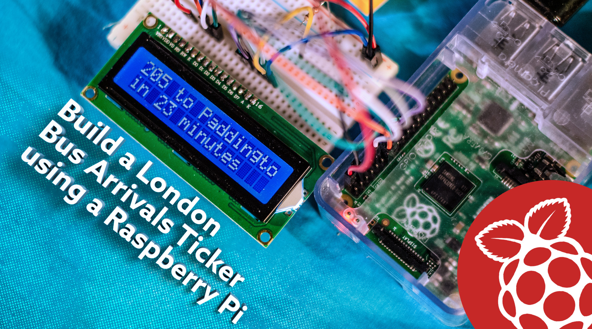
If you’ve ever had to wait for a bus in London, there’s a good chance you’ve used a TfL live bus arrivals ticker. If you haven’t, all you need to know is that it’s a rather long LCD screen that shows live arrival times for the next two buses at the bus stop. This is possible due to every bus in London being outfitted with a GPS module, allowing them to be tracked in realtime and enable arrival predictions.
In today’s tutorial, we’ll be recreating the live bus arrivals ticker using a Raspberry Pi and a cheap Hitachi 16×2 LCD character display.

Requirements

  • Raspberry Pi (any model will do)
  • 16×2 LCD with a Hitachi HD44780 controller
  • 1K Ohm minimum resistor (depending on your LCD module)
  • Potentiometer

Putting it together

There’s a variety of cheap LCD modules available on the market which you could buy. The cheapest ones are available on Amazon, but do not come with pins soldered. In that case you’d need a soldering iron to solder a header. Surprisingly, simply press pushing a header into the LCD doesn’t work, as the contacts seem to be on the top of the circuit board, as opposed to inside the holes. If you’d prefer a pre-soldered LCD, you can get one from Pimoroni. If you happen to own Adafruit’s I2C LCD modules (which also do require soldering), the wiring will be a lot less simpler and use a slightly different version of the code (more details below). Refer to this page for I2C wiring.

Apart from a soldered LCD module and a Raspberry Pi, you’ll need a 1K Ω resistor at minimum and a potentiometer. The resistor is important as some LCD modules don’t have a resistor for the backlight and hence, the current could increase to levels that are damaging to your Pi. Adafruit LCD modules always have a resistor, so that can be omitted in those cases. Finally, the potentiometer simply serves as contrast control.

An earlier version of this diagram incorrectly displayed wiring for the black GND wire to the RPi and lacked wiring for the potentiometer! Woops!

The code

The code for this project relies on two important modules. The first is a custom module I’ve written which allows us to parse information from the TfL API. In brief, it pings the TfL servers for a JSON file containing the buses arriving at the specified bus stop. It then creates an array of bus lines, arrival times, and destinations, and sorts them according to arrival times.

This is where the second module comes in to play, Adafruit’s Python Character LCD module, which allows us to communicate with these Hitachi HD44780 driven LCD modules. Surprisingly, this was the only module which worked with my LCD modules (both a cheap Facilla one bought from Amazon and one from Pimoroni), amongst the many other similar Python modules online. Before you can run my code, you’ll need to install the Adafruit Python module as follows:


sudo apt-get update sudo apt-get install build-essential python-dev python-smbus python-pip wget https://github.com/adafruit/Adafruit_Python_CharLCD/archive/master.tar.gz tar -xzvf master.tar.gz cd Adafruit_Python_CharLCD-master sudo python setup.py install

With the Adafruit module installed, you can move on to getting the code for the project from my GitHub page. Type the following commands at your terminal on your Pi to download the directory, and then run the script:


wget https://github.com/ismailuddin/raspberrypi/raw/master/ldn-bus-ticker/dist/ldn-bus-ticker.tar.gz tar -xzvf ldn-bus-ticker.tar.gz cd ldn-bus-ticker

To run the script, simply type sudo python ldn-bus-ticker.py N where N is the bus stop code for your bus stop. This bus stop code number is the unique number found at every London bus stop, which you text to 87287 to get live bus arrival times. Alternatively, if you’re using an I2C LCD module, type sudo python ldn-bus-ticker.py N i2c. And voilà, you’re very own London bus ticker is set up in your house, keeping you up to date on your favourite bus stop. You can find other bus stop codes to try from TfL’s website.

I hope you enjoyed this fun tutorial! If you have any suggestions or problems, drop a line below in the comments!


Comments

  • Pingback: When’s the next bus? with a Raspberry Pi | Raspberry Pi Pod()

  • Mike Crowe

    Hello, I’m getting an errno2 no such file or directory when running the sudo python tfl-bus-ticker.py N have followed your instructions exactly, any ideas?

    • Did all the previous commands run successfully, ie the wget… tar… cd..? Hence, after trying cd but before sudo python… If you just type ls, do you see a list of the all the files?

  • Krzysztof Sokół

    Hi,
    Great project! I got it working in no time, I have even managed to modify slightly your code for my needs, but I cannot figure it out how to utilise the Adafruit I2C LCD module’s buttons so I could flick between 2 different stops, i.e. Up for Eastbound Services Down for Westbound Services.
    Sorry for being a complete Python knob! https://uploads.disquscdn.com/images/a363fcad9c64b3596e6093446ba640525579abbeaee682318dcee830ae8609f9.jpg

    • That’s a nice idea to improve on this project! Do you mind sharing the code, and I could help you modify it to get it to work for this purpose?

      • Krzysztof Sokół

        import time
        import os
        import subprocess
        import Adafruit_CharLCD as LCD

        lcd = LCD.Adafruit_CharLCDPlate()
        lcd.clear()

        buttons = ( (LCD.SELECT, ‘Not in Use’ , (1,1,1)),
        (LCD.LEFT, ‘Westbound’ , (1,1,1)),
        (LCD.UP, ‘Not in Use’ , (1,1,1)),
        (LCD.DOWN, ‘Not in Use’ , (1,1,1)),
        (LCD.RIGHT, ‘Eastbound’ , (1,1,1)) )

        print(‘Press Ctrl-C to quit.’)
        while True:
        for button in buttons:
        if lcd.is_pressed(button[0]):
        lcd.clear()
        lcd.message(button[1])

        I was thinking that once button gets pressed your script gets called with a specific bus stop…
        I am a complete Python noob and would not have any idea on how to correctly implement it. I was also reading up on a waiting loop, so the script once ran would monitor if the button gets pressed and change the bus stop, again I have not got the slightest clue on how to do it.
        The only thing I have managed to do is to call your script by pressing the button, but once pressed it would not change to another…

        • Hi there, Sorry for the delay in getting back to you! Here’s a modified version of the file to run:

          https://gist.github.com/ismailuddin/3614d944c7ed264f85102ac113930bd7

          Run the file by typing the following at your terminal:
          $ python ldn-bus-ticker-2502018.py i2c

          and refer to the two different bus stop codes for the buses moving in opposite directions.

          The ‘i2c’ at the end is just to ensure the correct library for your LCD type is loaded. Let me know how it goes! Unfortunately I don’t have this LCD, so I can’t fully test it :/

          • Krzysztof Sokół

            Not a problem at all, it your time mate, which you have just devoted on some complete Python idiot!
            The script starts as normal with 2 arguments for 2 different bus stops, but then it goes into a loop similar to what my one did. Pressing the buttons does nothing… I have tried different buttons, just in case my soldering was not top notch (still much better than my Python skills), and ended up adding a different bus stop for every single button, but it still did not change the bus stops on press.
            When I however run the simple script posted above it seems to be reflecting the button presses and displays the relevant text.
            I will try to debug it later on and get back to you.

  • Steve Bunting

    I have the code working as bus times are reporting in my console, but not on my Hitachi Screen. I just have a row of blocks that can be dimmed using the varistor; which suggests that power and contrast are OK. Has anything changed in the last three years that would make this incompatible with a pi 3B? I have been reading about pin re-assignment. I’m a bit lost!

    • Hmm I don’t have a RPi 3B, however I’ve just noticed that Adafruit has deprecated the library I’ve used in this blog post in favour of their new CircuitPython based library. (https://learn.adafruit.com/character-lcds/python-circuitpython) I can’t seem to find any reference to the GPIO pins changing…It’s possible that the latest version of Raspbian is somehow incompatible with the old CharLCD library. Maybe see if you can get some basic text displayed with the new library? Otherwise, it might be a wiring or soldering issue? I had an issue at first where I hadn’t quite soldered it properly, and so some pins won’t working…

      • Steve Bunting

        Thanks! I’ve worked out the issue at my end. I read the wiring picture as some wires joined together, as you would read a cct diagram, but realised that can’t be the case. I tried green, yellow and purple as straight through wires and it works just fine now. User error in some ways, but as I normally use PCBs rather than point to point wiring I come with a different point of view. All’s well that ends well.