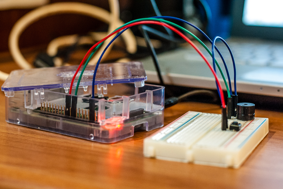
Christmas has just past, and according to Twitter it seems quite a few people people got a Raspberry Pi from Santa! Hence I thought, why not write a simple tutorial on how to make an alarm clock with a Raspberry Pi? You will of course require a few other parts; namely a buzzer, a switch, some leads to connect them up, and ideally a breadboard to avoid having to do any soldering. If you’re looking to buy these, then I’d recommend Monk Makes’ excellent ‘Raspberry Pi Electronics Starter Kit‘. Not only is it cheap as it comes with a variety of electronic sensors to play with (thermistor, light depended resistor, buzzer, LEDs, etc.) as well as the leads and the breadboard, but it also comes with an excellent set of project cards explaining how to set it all up as well as the accompanying code. Read on below to see how to get started!
Breadboard
If you’re new to electronics and the Raspberry Pi (RPi), you might not be familiar with the breadboard. The idea of the breadboard is to allow you to connect up electrical components without needing to solder wires or any other elaborate procedure. It’s basically a grid with many holes, into which you can plug jumper wires, and build circuits. A must requirement for anybody recently getting a RPi, and wanting to try out different projects!
The important thing to understand about the breadboard is how all the holes all connect up. First orient the breadboard with the short side horizontally, and the long side running vertically. In this orientation, the holes running in a horizontal line (the rows) are all connected to each other, with the exception of across the big indentation running down the centre. This gap allows you to connect items such as resistors across them, so that all the current is forced to pass through the resistors as opposed to through the breadboard as well. Looking down vertically, none of the boxes are connected, hence each row is it’s own independent line. On each side of the breadboard, there are two sets of columns with the ‘+’ and ‘-‘ symbols above them. These power rails are used to provide a power source (voltage) to the circuit. We won’t need these when using with a RPi, as the RPi will provide the power across the jumper wires.
The GPIO header
Before we start, its imperative you understand how the GPIO (general purpose input/output) header works on the RPi, as its vital to not only to know how to follow the tutorial, but also to make sure you don’t fry your RPi by using the wrong pins! The GPIO header is basically a set of pins, of which some are capable of sending and receiving current (the actual GPIO pins themselves), and the other’s serve a variety of purposes such as providing a ground (GND) wire. The actual GPIO pins are labelled simply with numbers (not on the RPi itself!), and are able to input or output a voltage of up to 3.3 V! This number is important, as some sensors may output more than 3.3 V, whilst other electrical components may not be able to handle a voltage up to 3.3 V. For this reason, it is extremely important that you use resistors where necessary to prevent exceeding this voltage barrier, especially when its being sent to the RPi! Some people recommend using a Pibrella breakout board, which basically connects on top of your GPIO header and ensures the voltage never exceeds this value. For our case today, particularly if you’re using the Monk Maker’s Starter Kit, we won’t need any resistors or have to worry about the voltage issue, as our components can work at up to 3.3 V.
Probably the most important thing to understand is how to read the GPIO header on your RPi, as the diagrams online don’t typically help you much with the orientation. Generally speaking, the first pin on the right side of the GPIO header (the 5V pin as seen on the RPi foundation website) is the pin which is near the corner of the RPi, facing the edge.
Final note, I’ll try to write this so its applicable to any electronics starter kit that you may have, but of course, different kits may vary and so things might be slightly different for you.
Project information:
Estimated project time: 10 minutes
- Raspberry Pi
- A buzzer
- A switch
- 3 male-to-female jumper wires, and 1 male-to-male jumper wire
- A breadboard
Step 1 – Connect up the circuit
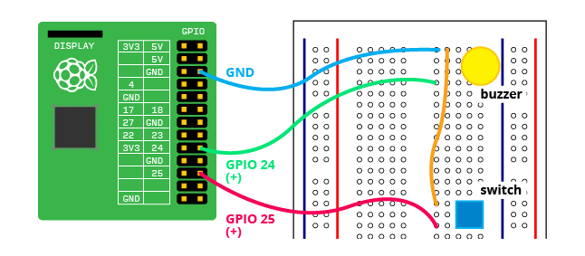
The GPIO header shown in the diagram is for the shorter version seen on the Raspberry Pi B models. The newer B+ model has a longer GPIO header, with more pins which continue in numbering at the bottom. The top half of header is identical for all RPi GPIO headers.
Plug in the buzzer into the breadboard, taking note of which leg is the positive lead. In the case of the Monk Maker’s Starter Kit, it is denoted by a’+’ sign on the top. In the same row as the positive lead, connect a green jumper wire to GPIO pin #24 (you may connect to any of the GPIO pins that can input or output a voltage, just make sure you write down which so you know which number to include in your code). Next, connect a blue jumper wire one in the same row as the negative leg. This will connect to the GND (ground) pin of the RPi which is at 0 V. This will ensure a 3.3 V potential difference (voltage) can be set up.
Plug in the switch somewhere down the breadboard. Some switches may have four connectors (see here for an explanation), but the Monk Make’s switch has only two. Those which have four are in fact really only two, since there are two pairs of legs. In any case, one set of legs must connect with a wire leading to ground pin, and the other with a GPIO pin. The orientation does not matter as it’s just a switch. Instead of using another GPIO GND pin on the RPi, we’ll just borrow the buzzer’s GND pin. To do this, simply connect a male-to-male jumper wire in the row between the negative lead of the buzzer and the wire leading to GND pin. Connect the other end of this wire in a row with one of the switch’s legs (pair). Finally, connect a male-to-female jumper wire (the red jumper wire) into the row of the switch’s other leg with GPIO pin #25.
Step 2 – Write up / Run the code
Python is the go to language for making projects with RPi, but you are free to use any other language you wish. If you’re feeling ambitious, you could try and figure out how to do code this yourself. Otherwise, you can find the code for the project below. I’ve saved this code as alarm.py.
# ~/raspberrypi/alarm.py
# Raspberry Pi Alarm Clock
# 2014, Ismail Uddin
# www.scienceexposure.com

import time
import RPi.GPIO as GPIO
from buzzer import buzz

GPIO.setmode(GPIO.BCM)
GPIO.setup(25, GPIO.IN, pull_up_down=GPIO.PUD_UP)

response = raw_input("Please input the time for the alarm in format HHMM: \n")

print("Alarm has been set for %s hrs" % response)
buzz(500,0.1)

alarm = int(response)
awake = 0

try:
    # Loop to continuously check time, buzz the buzzer for the set alarm time
    while True:
            # Continually get's the time as an integer value
            curr_time = int(time.strftime("%H%M"))

            # Buzzes the buzzer when the time reaches the set alarm time
            if curr_time == alarm:
                    buzz(10,0.5)
                    time.sleep(0.25)
                    buzz(20,0.5)
                    time.sleep(0.25)
                    awake = 1

            # Snoozes the alarm for 8 minutes from the current time
            # Only works whilst the alarm is buzzing
            if GPIO.input(25) == 0 and awake == 1:
                    alarm += 8
                    awake = 0
                    print(alarm)

            # If alarm continues past the set alarm time without being
            # snoozed, the alarm time is changed to the current time.
            # This ensures the alarm buzzes continuously until the
            # snooze button is pressed.
            elif curr_time != alarm and awake == 1:
                    alarm = curr_time
                    buzz(10,0.5)
                    time.sleep(0.25)
                    buzz(20,0.5)

finally:
        GPIO.cleanup()
        print("End")
You’ll also need an additional file which contains the code to make the buzzer make a sound. This code was originally written by Simon Monk, and was included in one of the scripts he wrote for his Starter Kit projects. We only need one function from that code, which I’ve kept in a separate file called buzzer.py. The code for this file is below:
# ~/raspberrypi/buzzer.py
# Script forked from Simon Monk's 'Pi Starter Kit' repo
# https://github.com/simonmonk/pi_starter_kit

import RPi.GPIO as GPIO
import time

GPIO.setmode(GPIO.BCM)

buzzer_pin = 24

GPIO.setup(buzzer_pin, GPIO.OUT)

def buzz(pitch, duration):
  period = 1.0 / pitch
  delay = period / 2
  cycles = int(duration * pitch)
  for i in range(cycles):
    GPIO.output(buzzer_pin, True)
    time.sleep(delay)
    GPIO.output(buzzer_pin, False)
    time.sleep(delay)
To ensure the code works, the file containing the buzz function code must be saved in the same directory as the other file and named buzzer.py. This is because the first code snippet has a line calling the module buzzer, which is the file buzzer.py.
Using our alarm clock!
If you’ve followed the tutorial properly, you should have your RPi set up as the diagram above, and have a directory on your RPi with two files, alarm.py and buzzer.py. To start your alarm clock, simply open a terminal and navigate to the directory where you’ve saved your two files. Then type in the following code: sudo python alarm.py. The code should start, and ask you what time to set as the alarm in format HHMM. Put in the time, and now wait till the time reaches your set time. To snooze the alarm, hold down the switch button until the buzzer stops. The new alarm time will be shown in the terminal. That’s it, your own home made alarm clock with a Raspberry Pi!
Limitations and improvements
Apart from the fact that is probably the most inefficient alarm clock in the world, considering it requires a computer with a 700 MHz processor, 512 MB of RAM and a micro SD card to operate, there are a couple of things that we could improve on this. As I’m not the world’s best coder, you could probably refine the code to be shorter and even more efficient. The current way it’s written means that you need to hold the snooze button down rather than simply press it once. This could potentially be overcome with multi-threading in Python. In the future, I plan to expand this project by incorporating an LCD screen with further buttons. Adafruit does an excellent 16×2 LCD screen for the Pi, which I’m hoping to get soon. Stay posted for an update to this tutorial sometime in the future!
I hope you enjoyed this simple tutorial for making an alarm clock with a Raspberry Pi. Drop a comment below for any suggestions, or if you’re stuck with the tutorial!
Update: An earlier version of this article featured a mistake in the code.
Comments
-
Nicole Swenson
-
Ismail Uddin
-
-
Dan
-
Ismail Uddin
-
-
tristan
-
Ismail Uddin
-
tristan
-
Ismail Uddin
-
tristan
-
-
-
-
Salman Bin Aman
-
-
dinie
-
Ismail Uddin
-
dinie
-
-
-
Salman Bin Aman
-
Ismail Uddin
-
-
Sebastian Garzon